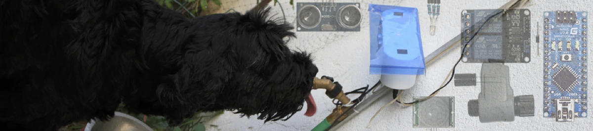
Dog Fountain
The garden's fountain for the dogs, based on Arduino.
Open-source hardware · Arduino
Introduction
The project started with two dogs in a garden and bowls that were always empty or filled with dirty water. Dogs like fresh water, and two 100-lb monsters can drink a lot of it — especially in the “hot” California climate.
My first approach was an “Outside Faucet Dog Waterer”: a mechanical valve fitted on a faucet and activated by the dog's tongue. The youngest dog tried, without consistent success, and usually ended up looking at me for help. The older one didn't even try to look at the valve.
With some training, both dogs could probably learn to use a mechanical valve — I just found it much more interesting to build something more intuitive for the dog. The experiment taught me a few things:
- It's not natural for a dog to walk up to a place with no water and push a “button” to get some.
- The youngest dog is always ready to try something new; the oldest one has strict manners — for him, a dog drinks from a bowl, not from a faucet.
- When a dog sees water, or hears it flowing, and he is thirsty, he comes to look — no training required. ;-)
At that point, the only solution was a robot to serve water to the dogs on demand. ;-)
Some ideas:
- Start the water when a dog approaches, to get his attention.
- Don't stop the water while the dogs are drinking (dogs have a moderate sense of humor).
- Stop the water when the dog walks away (the bill payer also has a moderate sense of humor).
- Place a bowl under the faucet, to respect “papa” dog's habit.
- Try not to overfill the bowl — ideally, balance the water output with the dog's intake.
- Keep the design simple, and simple to build.
The result
As of July 2014, the fountain had been running for almost a year and the dogs used it every day. It froze twice during the year; a simple power off/on fixed it each time.
Build overview
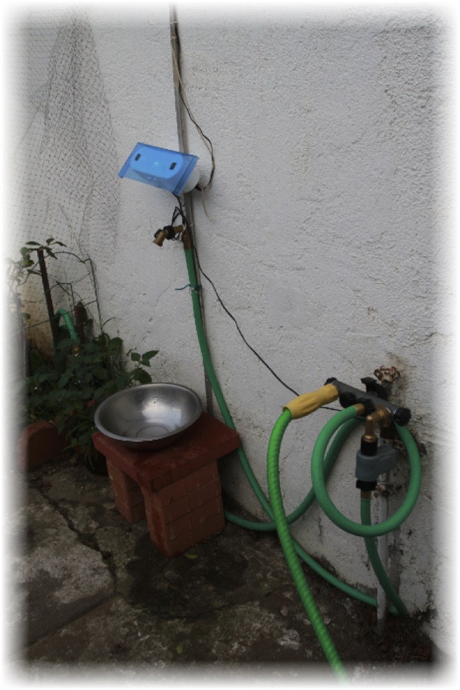
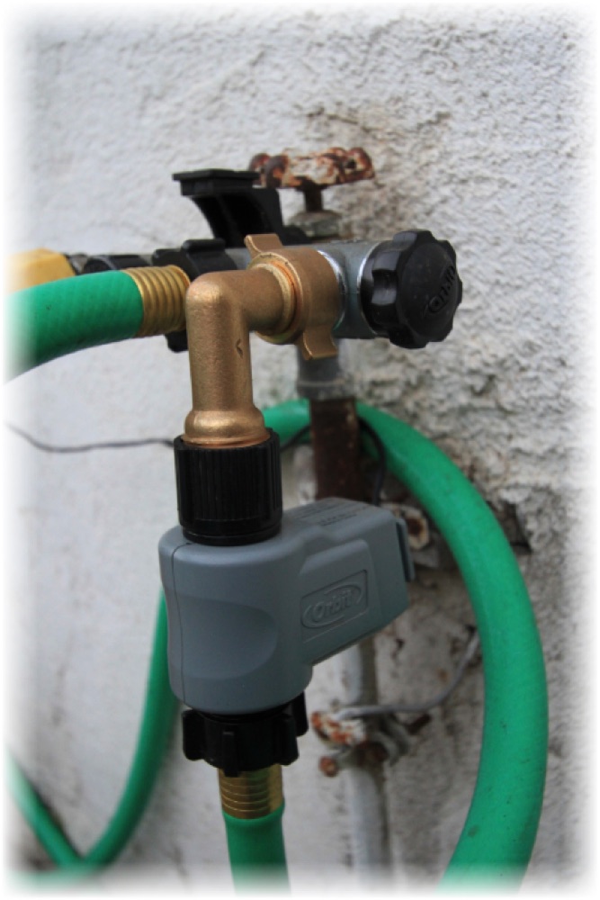
The existing wall faucet was too low for the dogs and too cluttered by hoses, so a garden hose is used to relocate the fountain. The fountain faucet sits on top of a bowl.
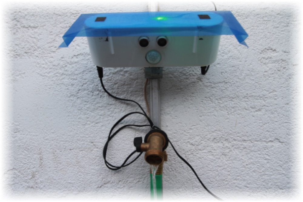
Water valve
Valve location
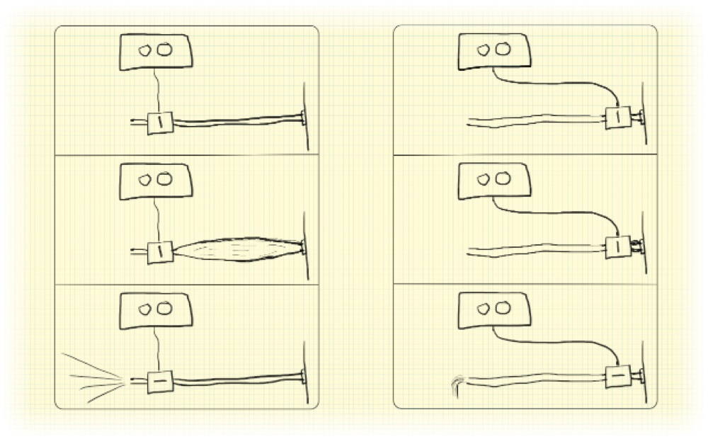
Initially the valve was positioned at the end of the hose, but when it closed the water pressure expanded the hose — and when it opened, the hose's elasticity plus the water pressure produced a small jet of water. The dogs did not approve.
Analysis of the valve
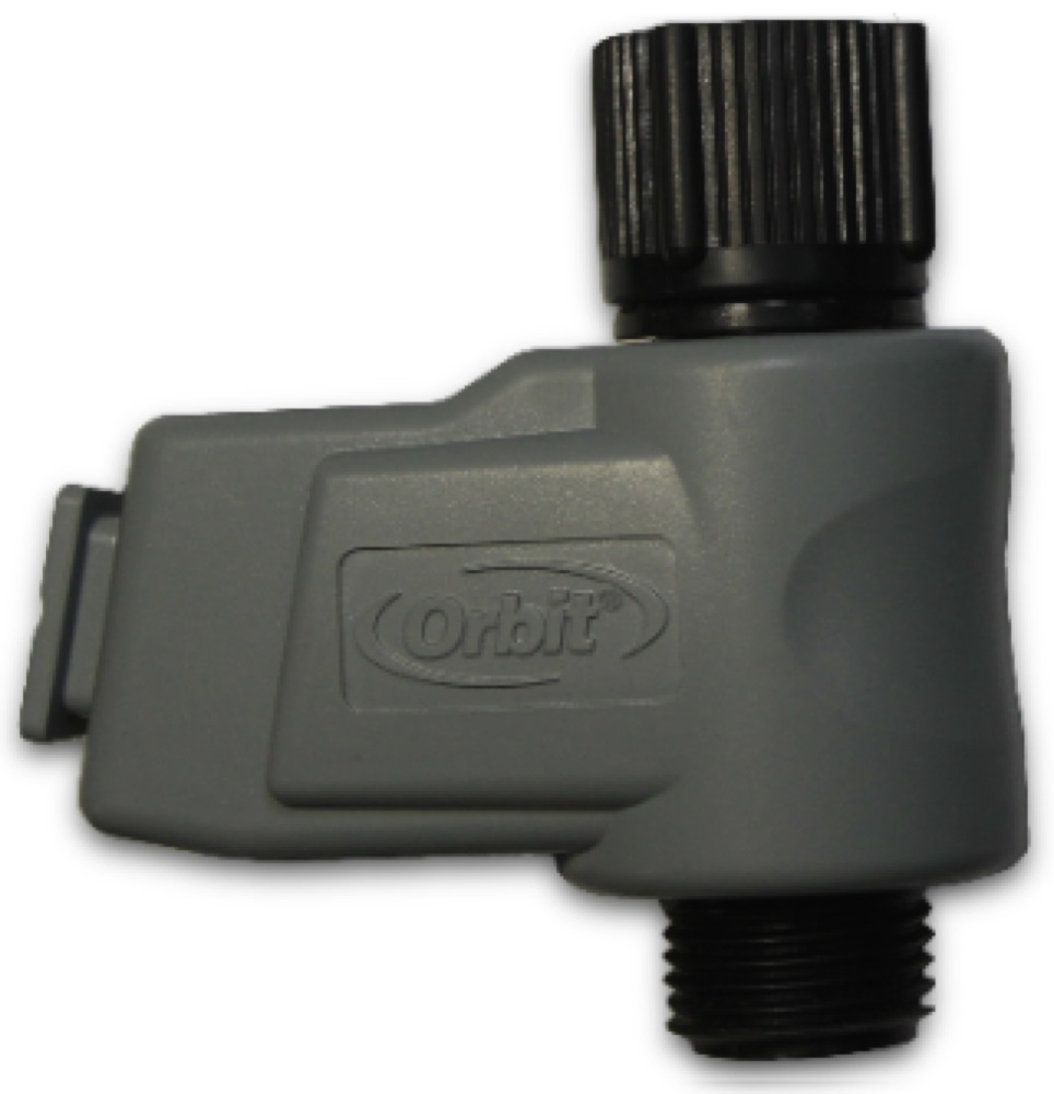
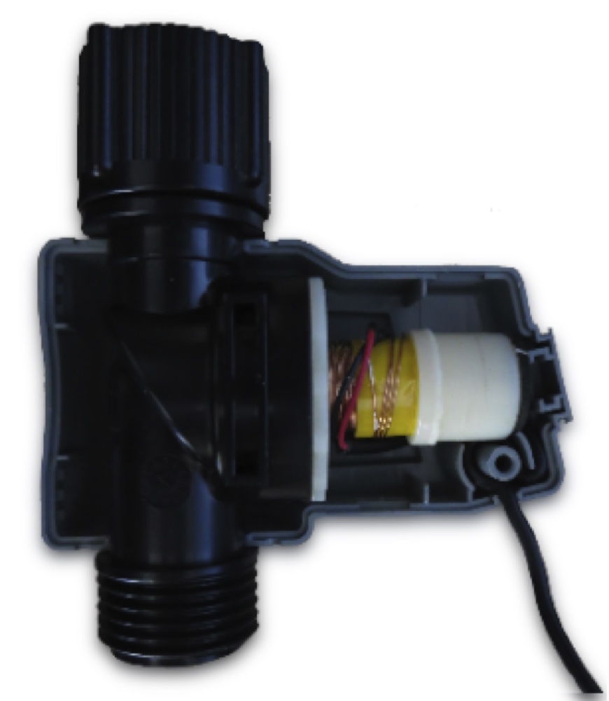
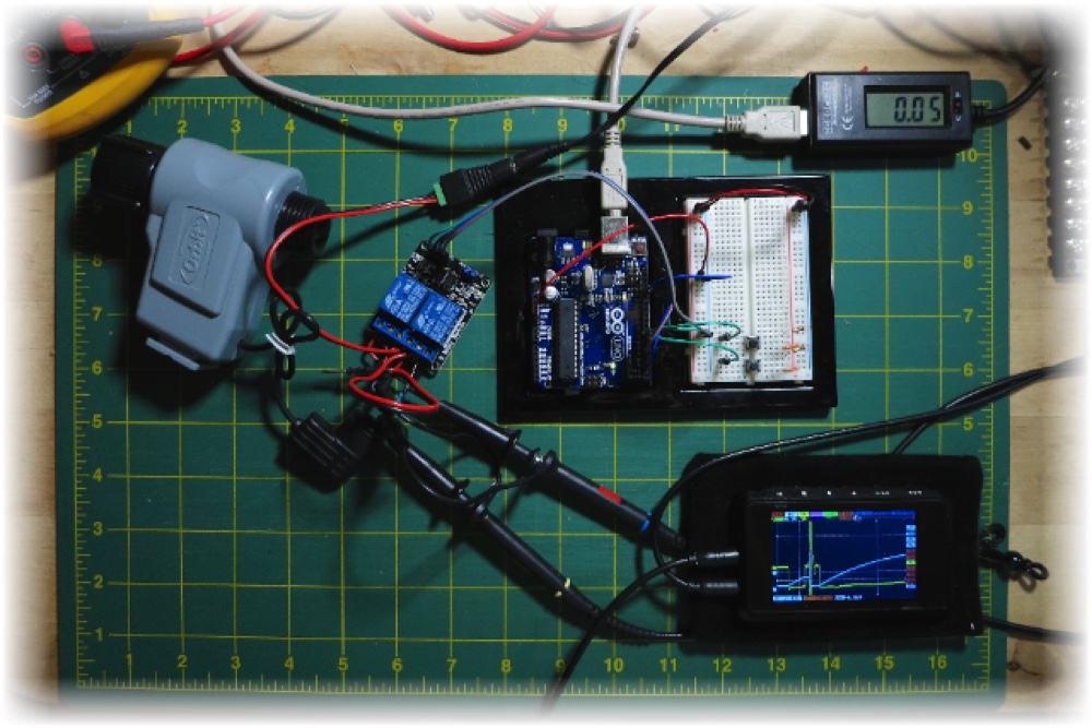
I used a valve I had in stock — inexpensive and easy to find in a store. It is designed for a battery-powered controller and has two stable states: a DC current pulse changes the state between open and close, and the polarity of the pulse sets the direction. Testing the solenoid at various DC voltages, it actuated down to about 11 V DC at roughly 1.4 A.
Current and voltage at the valve
On the scope captures below — yellow is the voltage at the valve, blue is the current.
Valve open
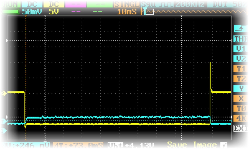
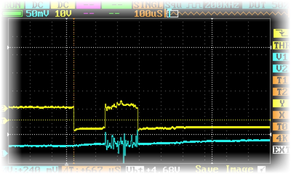
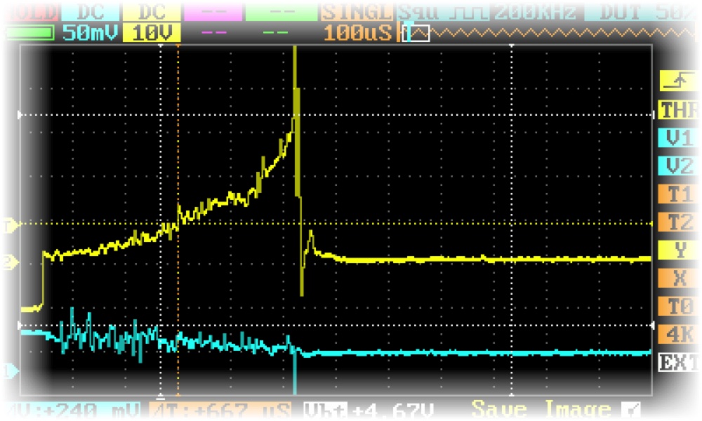
Valve close
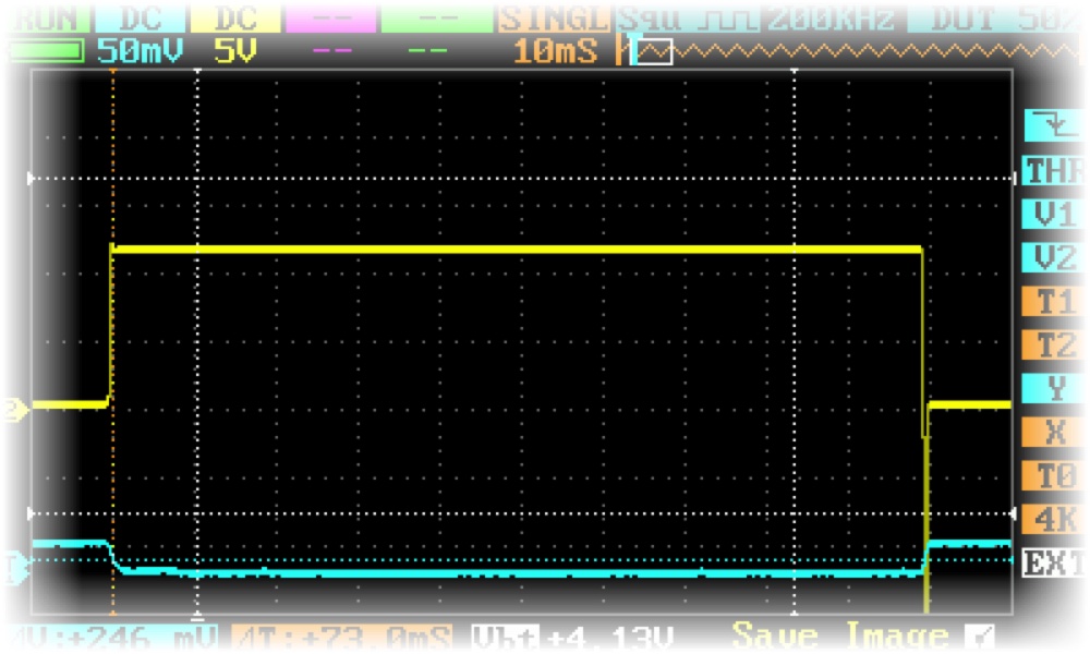
Timing
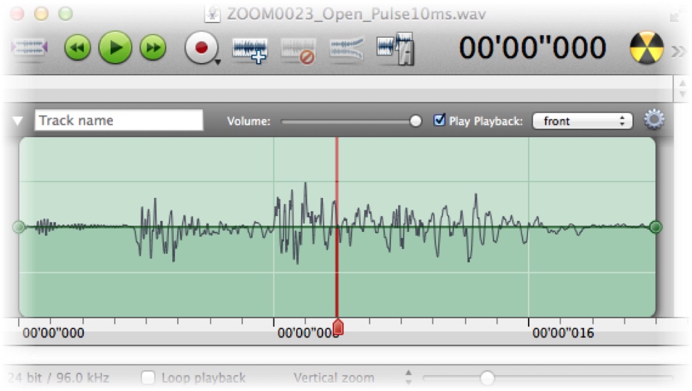
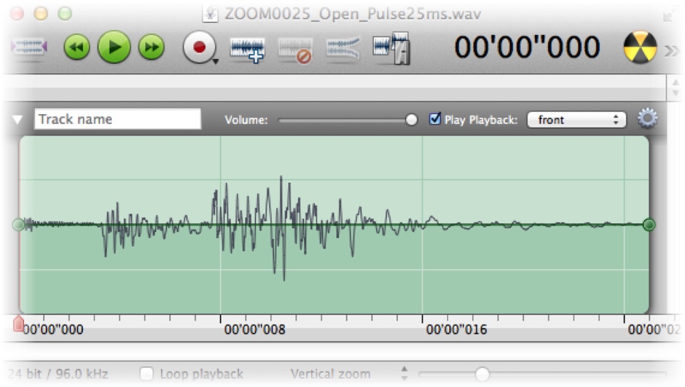
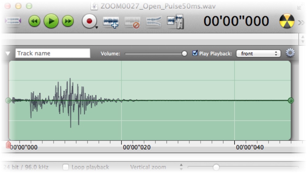
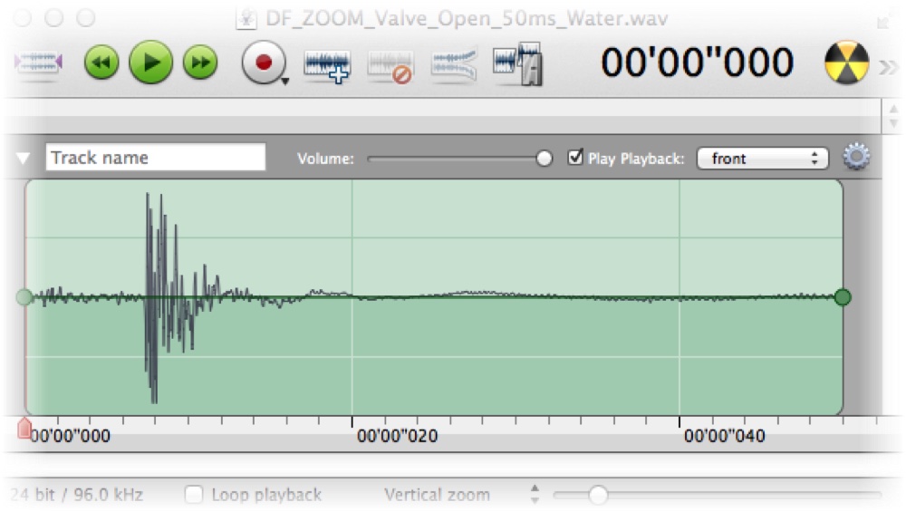
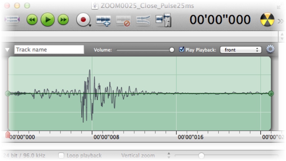
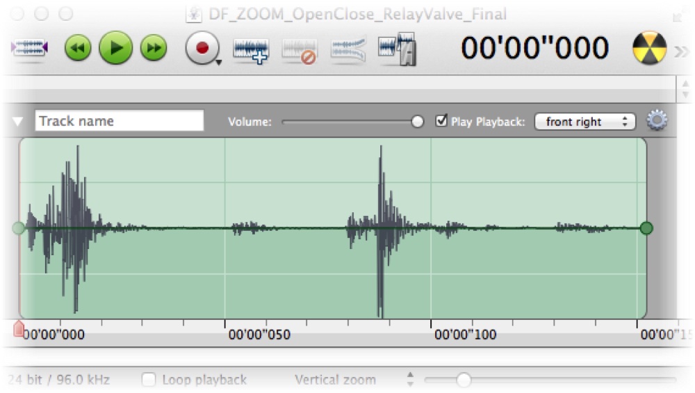
To estimate the pulse length needed to actuate, I recorded the valve's sound and compared, for different pulse lengths, the variation of the sound envelope.
Valve open
Analysis:
- The 10 ms pulse, compared to 25 ms, shows missing power in the second part of the sound wave — 10 ms is too short.
- 25 ms versus 50 ms shows no improvement.
- The presence of water flow does not seem to affect the duration.
Valve close
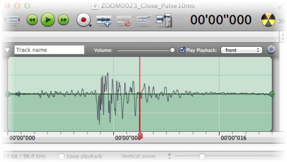
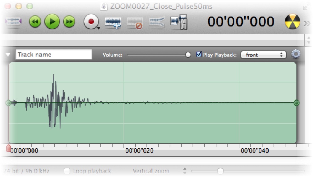
The close pulse shows no difference from the 10 ms pulse onward.
Detail of a 50 ms pulse
These captures show a 50 ms pulse for open and close. First, only the relay sound is recorded — in order: relay 1 open, close, relay 2 open, close. We can verify the time between the relays: open-to-close is timed to 50 ms.
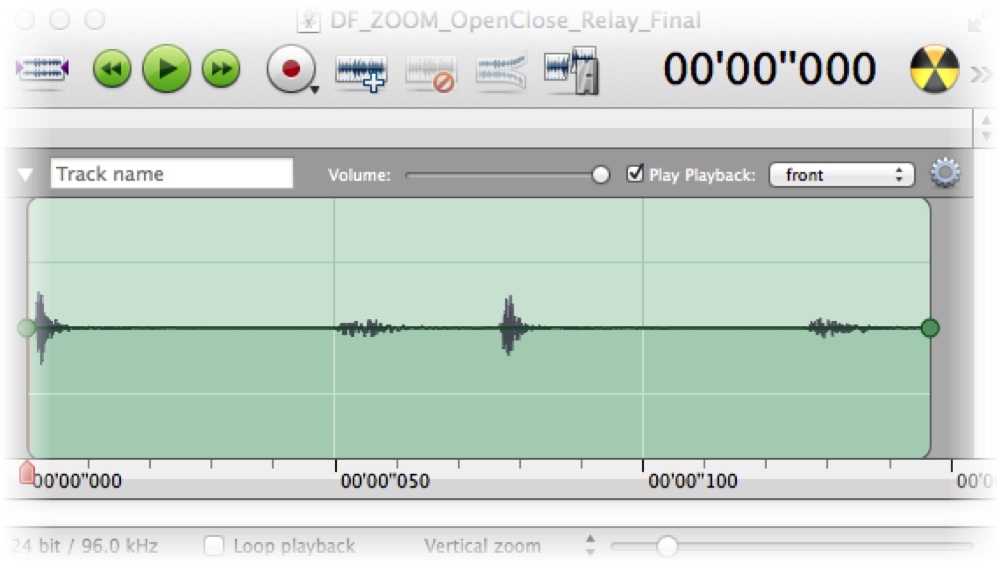
Then the relay and valve are recorded together, with the same sequence. We can see the much stronger noise created by the valve just after the relay actuates, and verify the margin between the pulse duration and the valve's movement.
Conclusion
A 20 ms pulse should open the valve and a 10 ms pulse should close it. Closing matters most — it avoids leaks — so it deserves plenty of margin. To keep it simple, I set the pulse to 50 ms in both directions. The valve rarely actuates and lives outside, so solenoid temperature is not a problem.
Valve connector
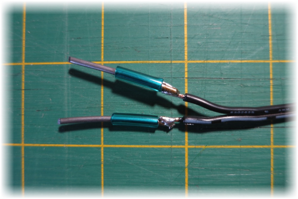
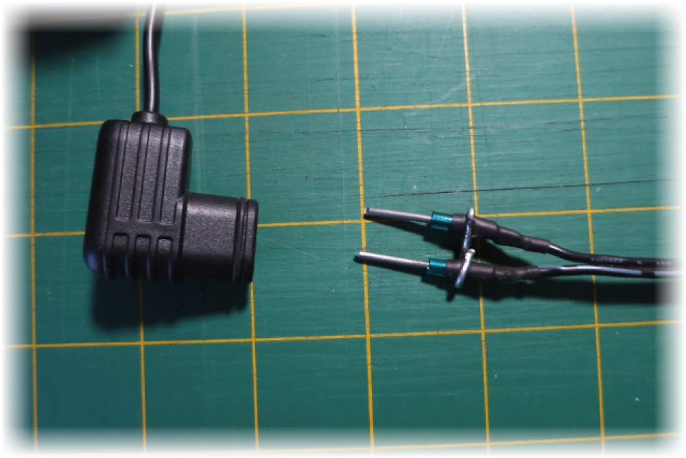
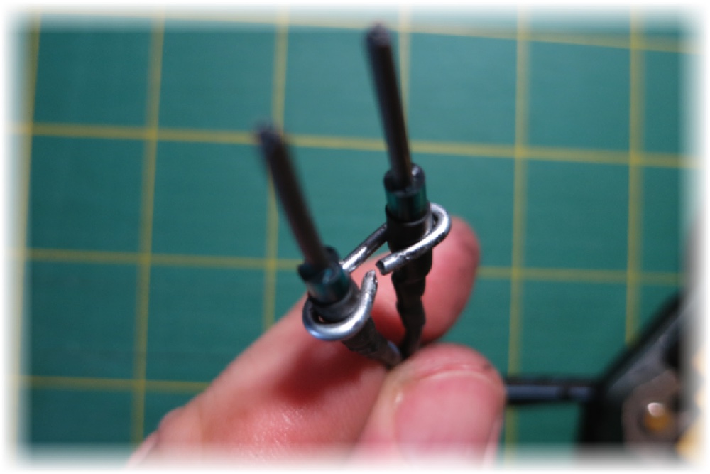
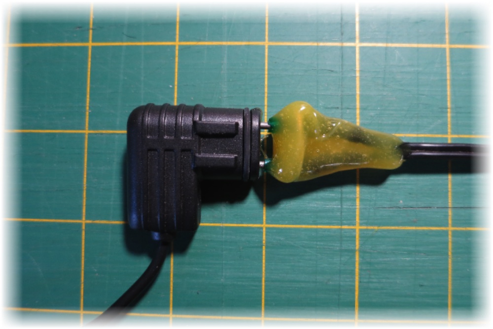
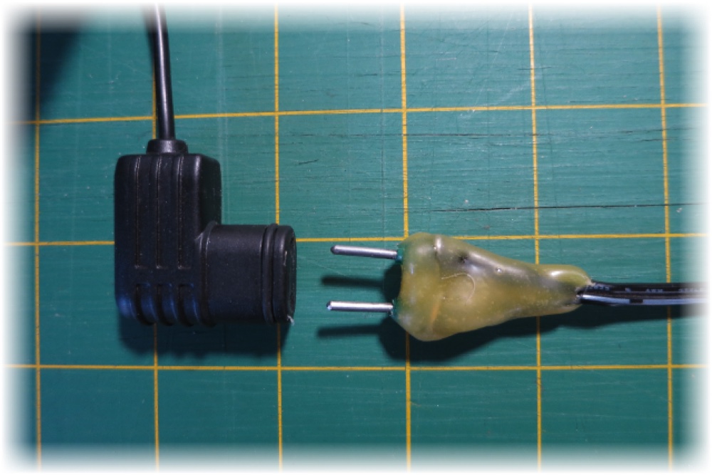
The Orbit valve has a very small power cable; I needed a little more. The valve connects to a male connector not available in a store, but making one is pretty simple:
Valve relay
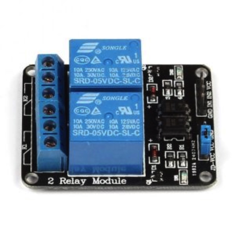
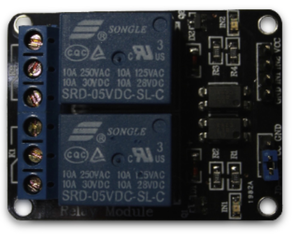
The relays commute the valve — a simple way to switch 12 V at 1.5 A. Each relay has a normally-open and a normally-closed contact; pulling IN1 or IN2 low switches it. Two relays generate the three states needed: open pulse, close pulse, and stay.
Valve connection to the relay
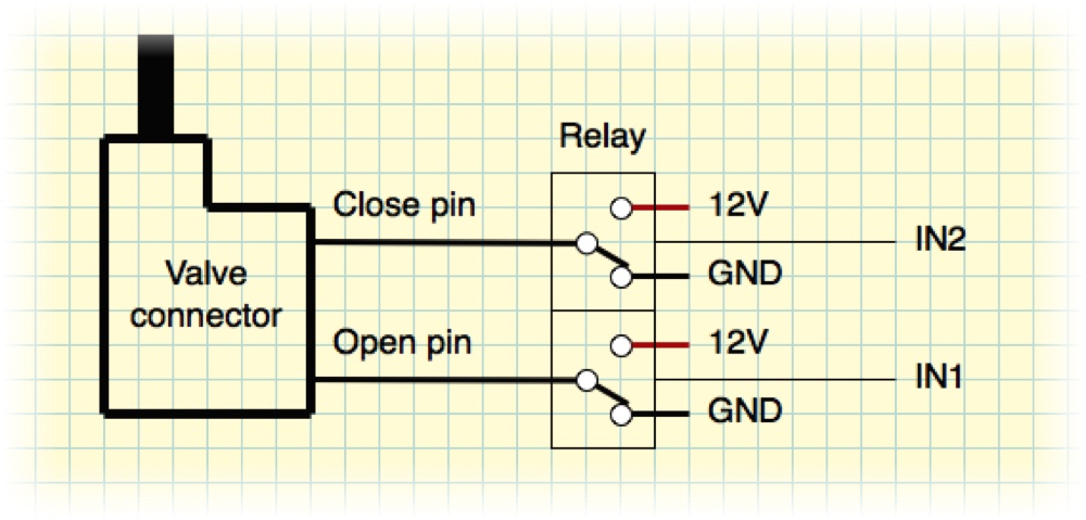
| IN1 | IN2 | Open pin | Close pin | State | Description |
|---|---|---|---|---|---|
| Low | Low | 12 V | 12 V | Stay | Keep valve state (not used) |
| Low | High | 12 V | GND | Open pulse | Valve switches to open |
| High | Low | GND | 12 V | Close pulse | Valve switches to close |
| High | High | GND | GND | Stay | Keep valve state |
Sensors
Proximity — HC-SR04 ultrasonic
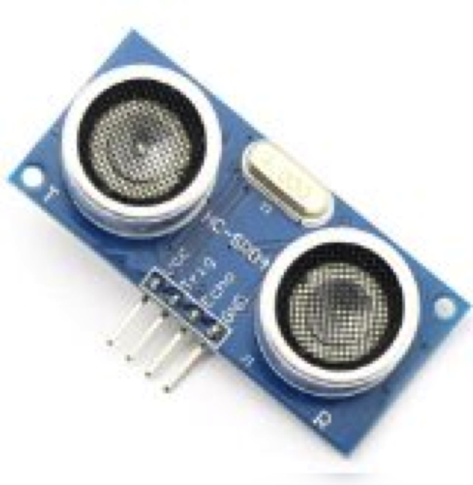
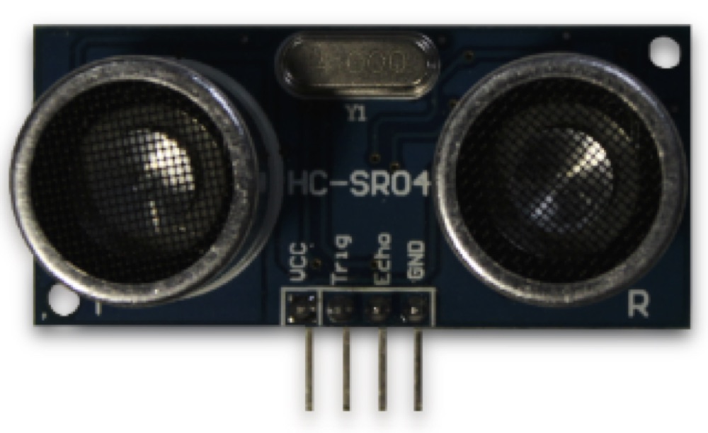
The HC-SR04 is inexpensive and popular, measuring distance from about 2 cm to 3 m or more over a narrow ~2° beam. It emits an ultrasonic ping and times the echo, like an active sonar. Drawbacks: it's active (uncertain lifespan under continuous use), a fly moving in front can trigger a false positive, and the dogs seem to hear it. Upsides: returning an actual distance is perfect for finely controlling the valve — and the dogs hearing the ping can learn to associate it with “water is here!”.
Motion — HC-SR501 PIR
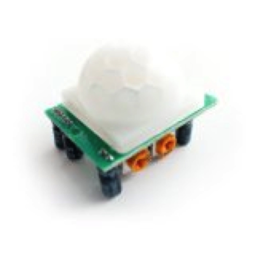
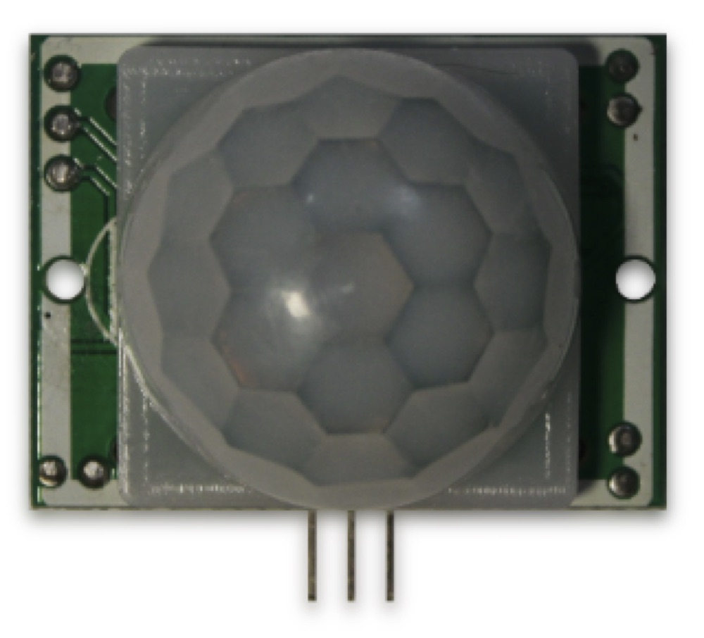
The PIR is also cheap and popular, sensing the motion of a heat source up to ~6 m over a wide ~180° area. Drawbacks: it only detects movement (when a dog stops to drink, detection stops), it's sensitive to unwanted heat movement outdoors (hot air, moving shadows) so it produces false positives, and it gives only a basic “motion detected” with no direction. Upsides: passive, silent, likely long-lived, and its wide field of view spots a dog coming from far away.
Using the two together
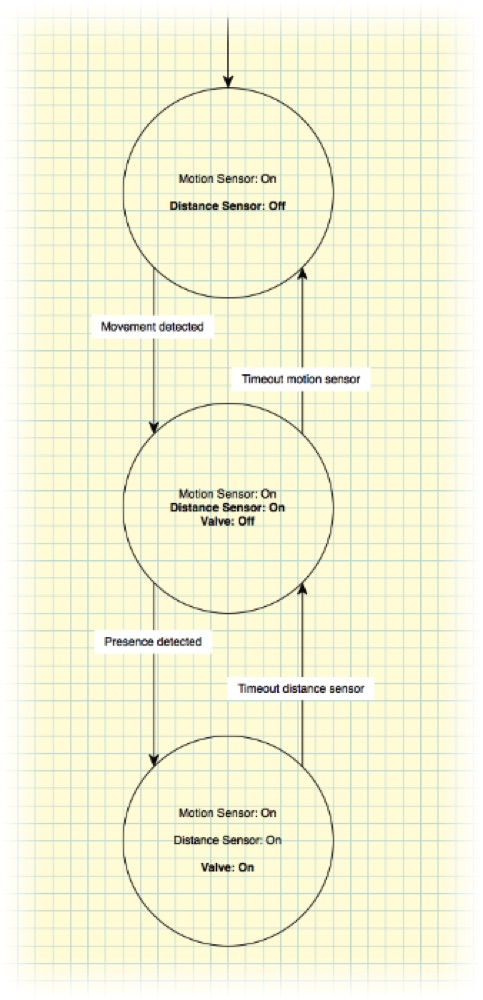
The idea is to pair the two sensors. The ultrasonic sensor starts off; the PIR scans the area. When a dog approaches, the PIR wakes the ultrasonic sensor; when the dog reaches the fountain, the ultrasonic sensor triggers the water; when he leaves, it stops the water; and after a while with no movement, the PIR lets the ultrasonic sensor sleep again.
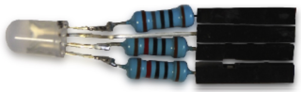
Feedback — RGB LED
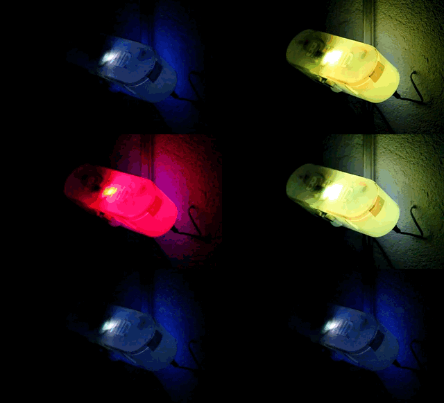
The LED is very useful for debugging the fountain's code. When several sensors trigger at once, the highest row in the table wins:
| Light | Meaning |
|---|---|
| Green | Near presence detected (ultrasonic) |
| Yellow | Far presence detected (ultrasonic debug) |
| Red | Motion detected (PIR) |
| Blue | PIR recently triggered, but no more |
| White, pulsing | Fountain is sleeping |
| Black | Do you have power? |
The Arduino Nano can supply up to 40 mA per pin; about 9 mA per color is plenty here. From each color's forward voltage, the resistors work out to 180 Ω (red), 100 Ω (green), and 100 Ω (blue).
CPU
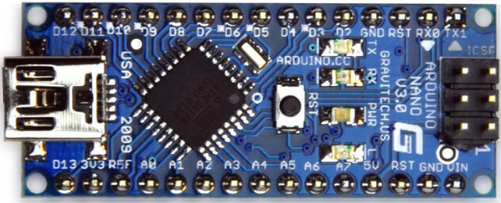
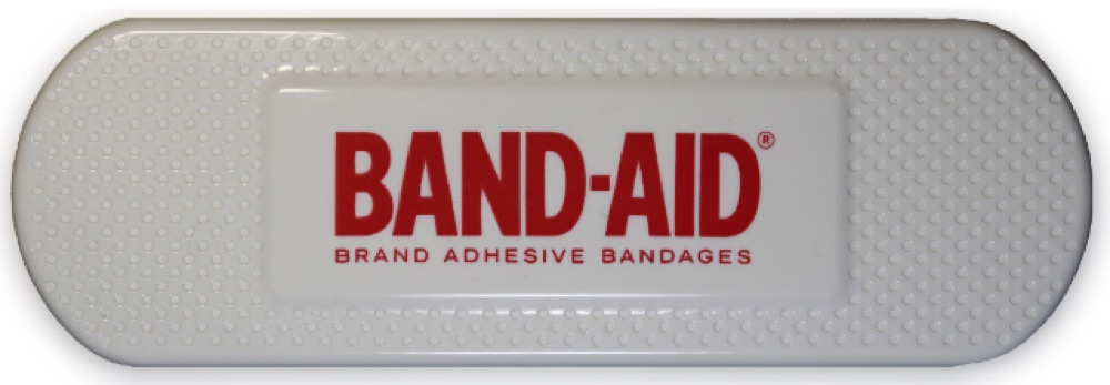
Fountain body
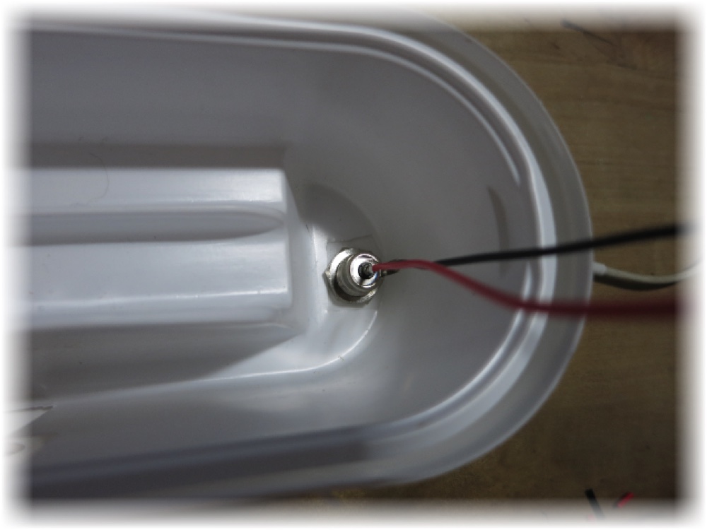
Power supply
Schematic
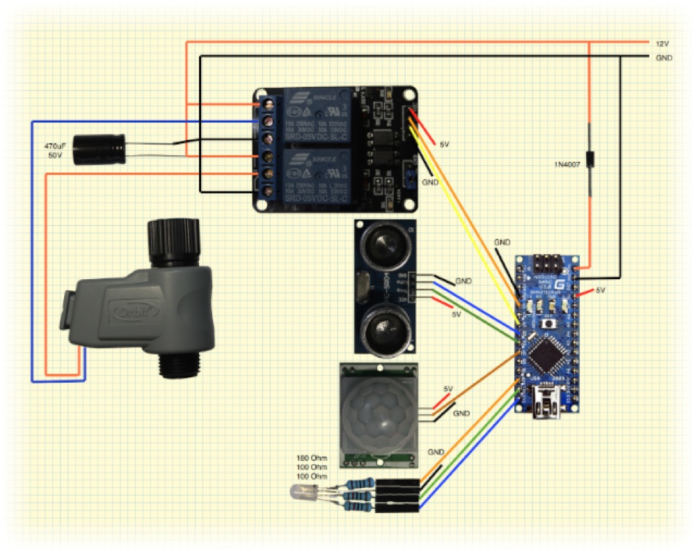
The schematic is simple and needs only a little soldering. A 470 µF capacitor was added on the valve's power line: it provides a reserve of energy for the valve and removes the visible back-EMF from the power line — without it, the Arduino is completely unstable. (The capacitor can't sit directly on the valve because of the polarity inversion.)
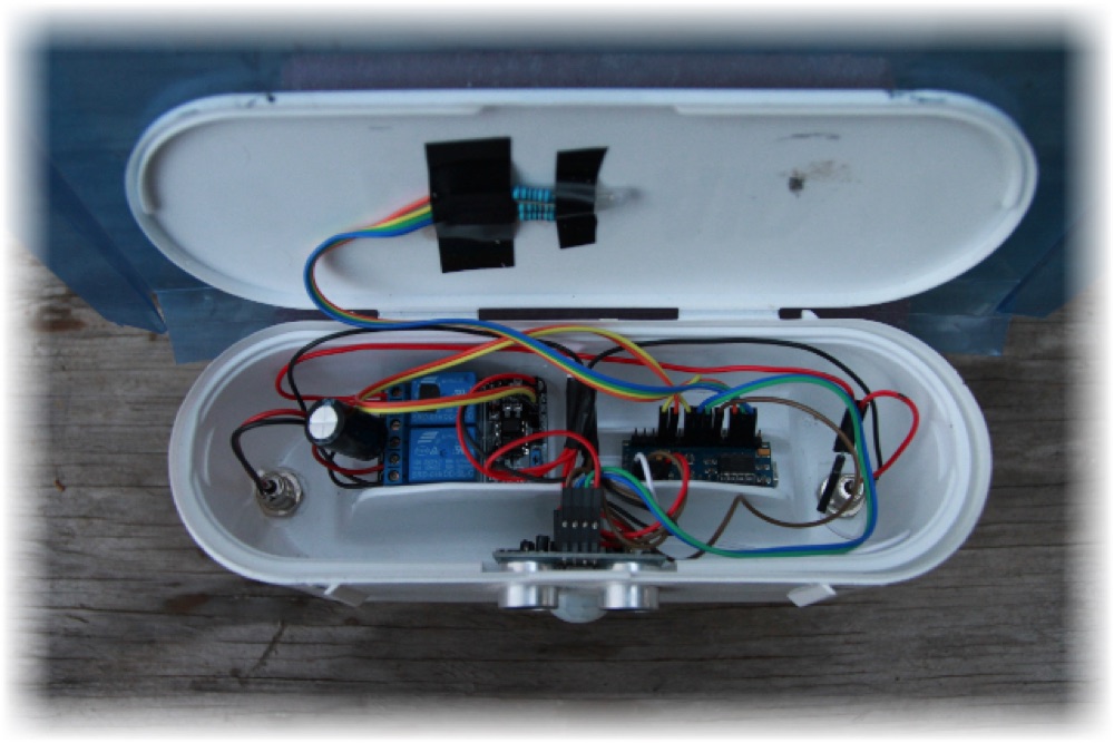
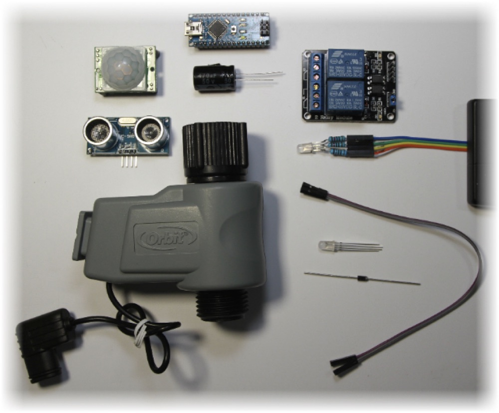
Parts & cost
| Part | Reference | Qty | Price |
|---|---|---|---|
| CPU | Arduino Nano v3.0 | 1 | $13.99 |
| Valve | Orbit extra valve | 1 | $13.56 |
| Relay | 2-channel relay module | 1 | $7.18 |
| Power supply | DC 12 V 1.5 A | 1 | $7.00 |
| Connector | 2.1 × 5.5 mm DC power jack, female | 2 | $5.32 |
| Sensor | HC-SR04 ultrasonic distance | 1 | $3.13 |
| Sensor | HC-SR501 PIR | 1 | $2.67 |
| Components | Resistors (1×180 Ω, 2×100 Ω) | 3 | $0.10 |
| Component | RGB LED | 1 | $0.05 |
| Component | Capacitor 470 µF | 1 | $0.03 |
| Cable | Female-to-female jumper wires | 1 | $0.80 |
| Box | Costco Band-Aid box (recycled) | 1 | $0.00 |
| Total | $53.83 |
Prototype & test
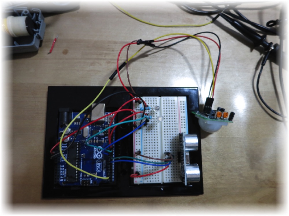
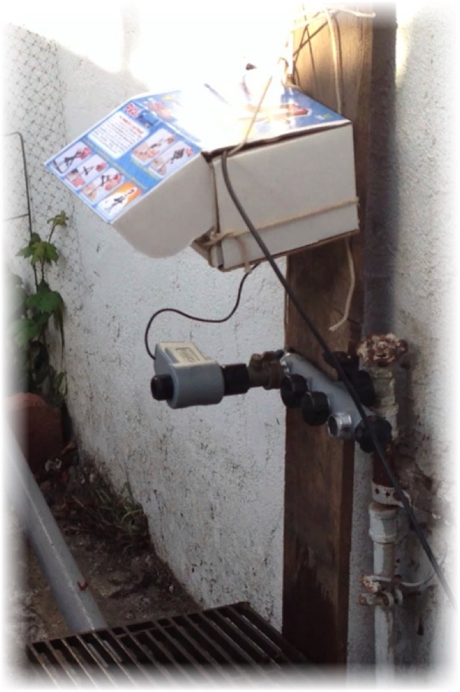
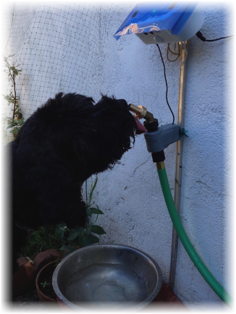
Comments
That's just cool 🙂
I know that some people make everything very accurate — and that one is the proof 😉
I did not expect to find a graph from an oscilloscope in such a project. However, I am sure your dogs don't mind and they will have fresh water all the time. How about a level sensor on the bowl and stop the fountain when there is enough water in the bowl? I mean, you need to pay the water, and even a bowl each day will make a difference over one year.
— from the Let's Make Robots community
Specs
- Actuators / output: valve
- CPU: Arduino Nano 328
- Operating system: Arduino
- Power source: 12 V DC
- Programming language: sketches
- Sensors / input: SRF05 ultrasound, PIR sensor
- Target environment: outdoor