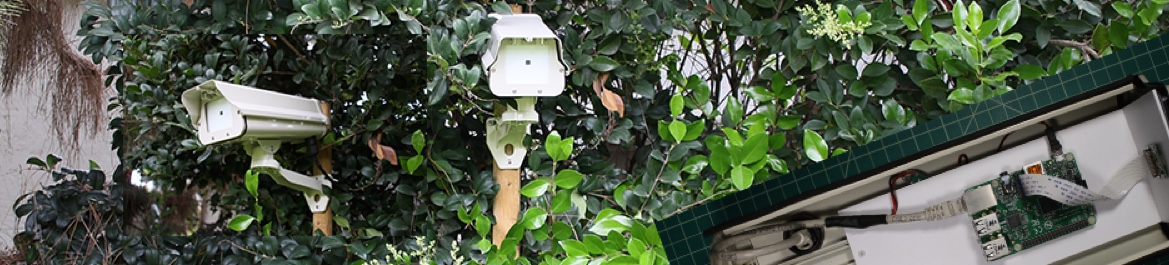
Picammory Mark II
The garden's camera based on Raspberry Pi — with motion detection.
Open-source hardware · Raspberry Pi · GPL-2.0
Introduction
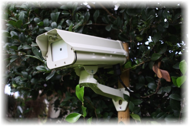
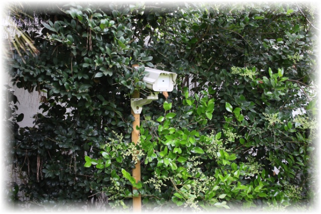
This project builds a waterproof, high-definition camera. The camera:
- Takes an hourly full-definition picture of the garden
- to create high-speed movies of the garden over the years,
- to see how the garden changes under different watering settings;
- Detects and records intrusions in a noisy environment (trees, leaves, wind, sun…)
- for security,
- for watching the squirrels.
Picammory has the following capabilities:
- Captures one full-size image every hour
- A mix of Python 3 and C for fast image processing — 100 ms capture, 26 ms processing
- Records continuous HD video in memory, keeping ~10 s before the trigger event
- Uploads movies to an FTP server
- Automatic start at boot, and auto-restart after a crash (
restartd) - Automatic
h.264 → mp4conversion for easy viewing on Mac/PC - Bonjour to advertise services, and AFP file sharing with the Mac
A 5-stage motion-detection algorithm
- A moving average of the previous images (with low memory usage)
- The difference between that moving average and the current image
- A moving-average mask to automatically remove noisy pixels
- Surface detection to convert adjacent pixels into surfaces (a very efficient algorithm)
- Surface processing to detect motion
Hardware build
Camera body
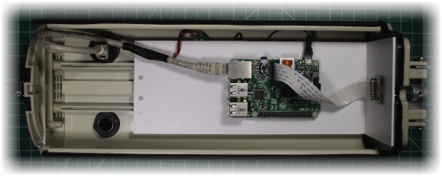
The body is an aluminium housing with good waterproofing and an excellent two-axis orientation system. The inside is very roomy — a platform on a rail secures the circuit board.
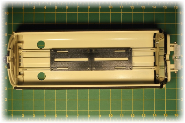
Component platform
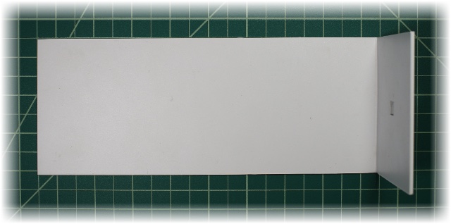
The Raspberry Pi and all future components sit on a platform cut from a 0.080″ styrene sheet, so the Pi is easy to insert and remove. From a 12×12″ sheet I cut a 3.5″ (90 mm) band.
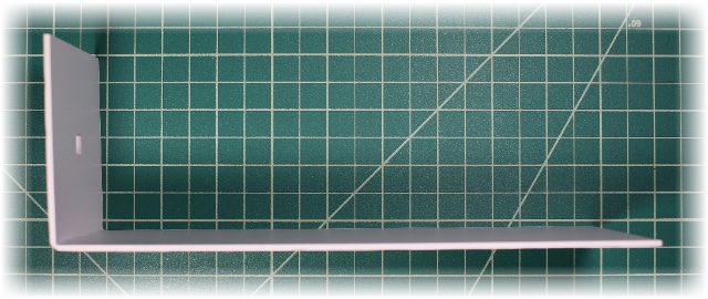
I bend one end to a 90° angle — this forms the front that covers the body's window. Bending is easy once the styrene is warmed with a heat tool (a Portasol 75 W).
Camera mount
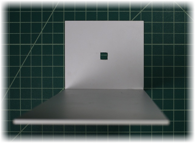
A square hole is drilled in the middle of the platform to hold the camera — roughed out with a Dremel and a 194 high-speed cutter, then trued up with a precision blade (an X-ACTO).
Raspberry Pi attach
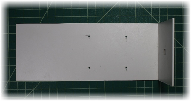
The Pi is centred on the platform, at a comfortable distance for the camera cable. I drill four holes with a No 43 drill and tap a 4-40 NC female thread. To avoid a misplaced hole, test-fit the Pi after each drilling.
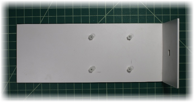
Screw in the four nylon hex standoffs (#4-40, 1/4″).
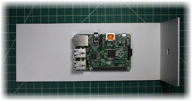
Put the Pi on the standoffs, secure with four screws, and check that everything fits.
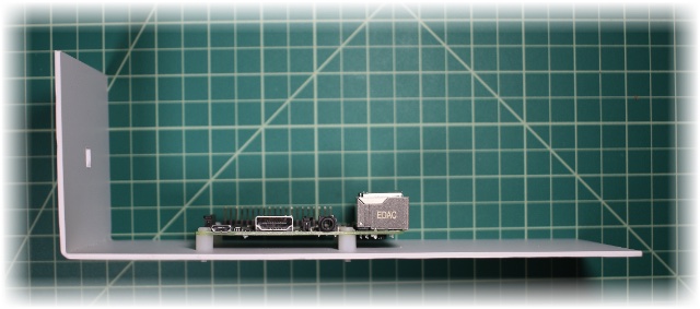
Cut off the small part of the standoff screws poking through the styrene, or they will stop the sheet from sitting flat on the camera platform. (Alternatively, invert the order — make the Pi attach and the camera platform together, and drill the standoff holes through both.) The Pi is set; remove it and keep it safe until the final integration.
Component platform on the rail
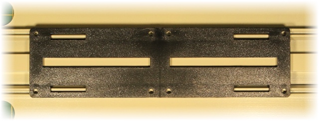
The component platform is fixed on top of the camera's rail platform. The camera's existing 8 holes are hard to use — they're in direct contact with the rail, with no room for a nut or screw head — and because a fair bit of force is needed to unclip the platform from the rail, I add nuts here.
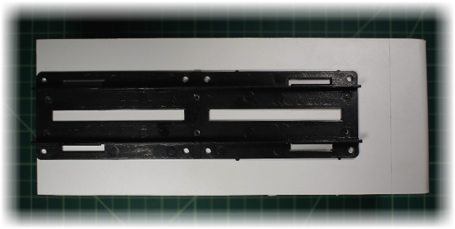
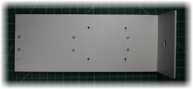
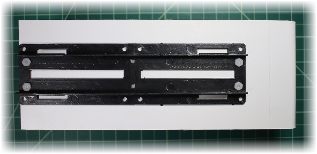
The camera platform sits under the component platform, centered in width but aligned to one end to limit traction when it's unclipped from the camera. The plan: drill six holes, tap a female thread, plus four nuts at the end.
Normally it's a bad idea to assemble several pieces with female threads — it's hard to make it right and tight through all layers; better to leave the holes un-threaded and use nuts. But here the plastic is malleable and I tap all the pieces at once, so it's fine, and more threads give a better coupling. Using a No 43 drill and a 4-40 NC tap: drill the left (border) hole first, tap it, and bolt it to hold position; do the same for the opposite diagonal hole; now that everything is held together, safely drill the four remaining holes.
Waterproof Ethernet connector
The first version was weak on waterproofing where the network cable entered; the second uses a waterproof RJ45 coupler.
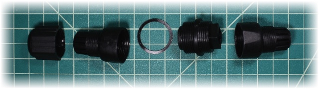
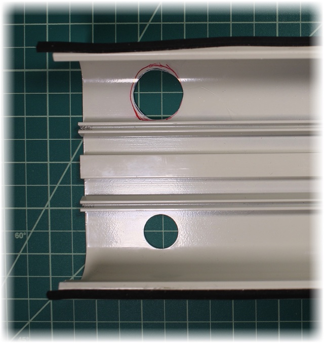
The body's existing hole is 18.9 mm and the coupler is 25 mm — a bigger hole is needed. The box is 1.2 mm aluminium, so a Dremel with the 194 cutter handles it easily.
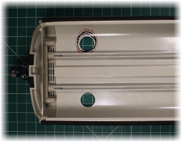
The rail blocks a symmetrical expansion, so the hole must be shifted. Before removing any metal, draw the part to remove carefully — here, black is the metal to cut and red the limit not to pass.
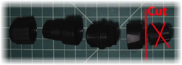
The coupler is made to join two Ethernet cables and waterproof both sides; since one side sits inside the already-waterproof box, I remove that side's seal for a lower profile.
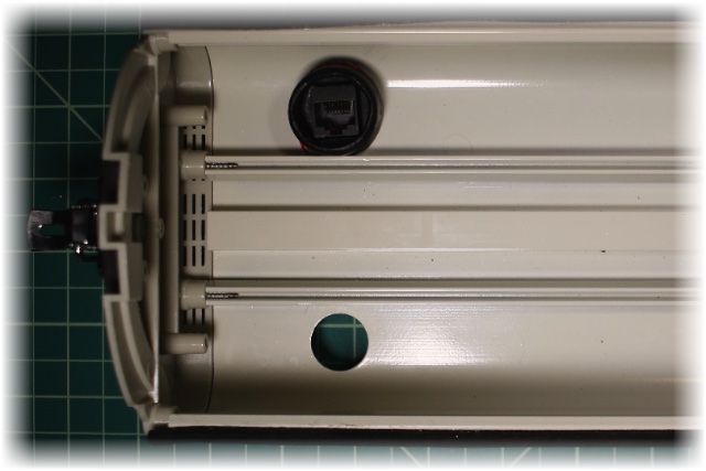
Power over Ethernet
Standard Power over Ethernet is complex and expensive; a non-standard “passive” PoE is friendlier. 10Base-T and 100Base-T need only 4 of the 8 wires — the other 4 are free.
| RJ45 pin | Wire colour | Wire Diagram | 100Base-T | 1000Base-T |
|---|---|---|---|---|
| 1 | White/Green | Transmit+ | BI_DA+ | |
| 2 | Green | Transmit− | BI_DA− | |
| 3 | White/Orange | Receive+ | BI_DB+ | |
| 4 | Blue | Unused | BI_DC+ | |
| 5 | White/Blue | Unused | BI_DC− | |
| 6 | Orange | Receive− | BI_DB− | |
| 7 | White/Brown | Unused | BI_DD+ | |
| 8 | Brown | Unused | BI_DD− |
The passive PoE injector uses the 4 remaining wires to provide power, grouping them by two:
| Wire | Connected to | Provides | |
|---|---|---|---|
| 4 (Blue) | + | 5 (White/Blue) | DC + (12 V) |
| 8 (Brown) | + | 7 (White/Brown) | 0 V |
The Pi needs 5 V, but 5 V can't be carried over a long distance (voltage drop) — usually 24 V or 48 V is used. Since the camera isn't far and the Cat6 is 23 AWG, I opt for 12 V DC; the DC/DC converter in the camera takes 5–23 V in and outputs 5 V.
Passive PoE injector
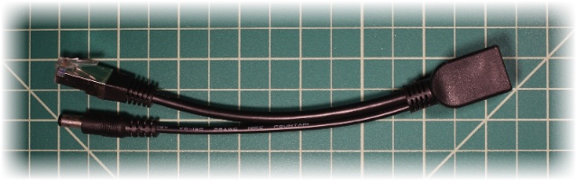
On the router side, connect the passive PoE injector/splitter between the router and the cable to the camera, and connect a 12 V DC supply to its DC connector.
Passive PoE splitter
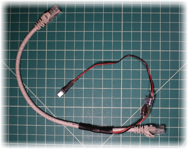
The same cable can extract the power, but the off-the-shelf splitter is bulky and doesn't provide the micro-USB the Pi needs — too complex for the camera side. Instead I make a compact custom splitter.
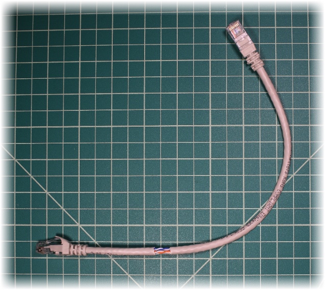
Start with a 1-foot Ethernet cable and remove a band of the outer sheath near one end.
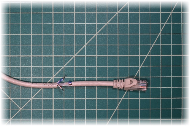
Cut the Blue and White/Blue and solder them together; cut the Brown and White/Brown and solder them together.
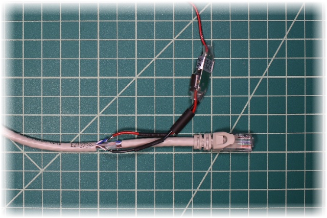
Take the DC/DC converter, slip a small heat-shrink onto each power cable and a bigger one over both. Solder the Blue to the converter's Red , and the Brown to the Black .
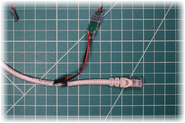
Cover both power wires and shrink; do the same with the bigger tubing over the pair. Small tubings also go on the four remaining cut wires.
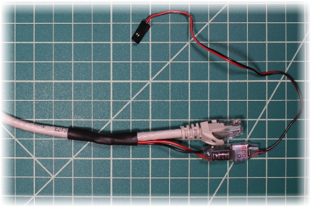
Finally, a big tubing covers all exposed wires.
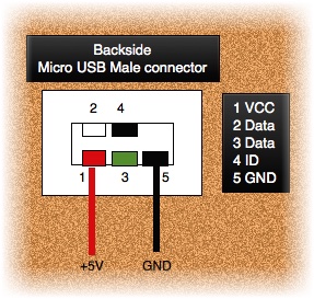
On the other side of the converter, cut off the supplied connector and replace it with a micro-USB.
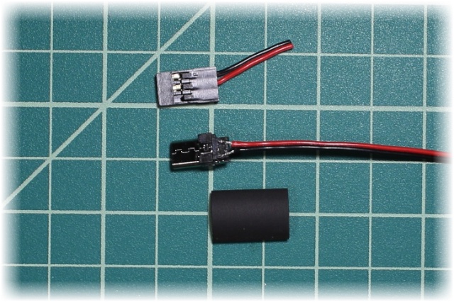
Solder the red and black wires to pins 1 and 5. Pins 1, 3 and 5 sit very close together — to avoid bridging pin 3, just cut it off the connector.
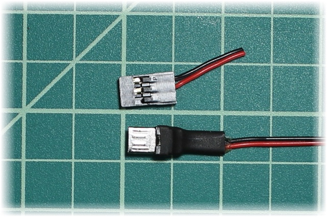
Add a little hot glue on the micro-USB pin and cap it with heat-shrink.
Camera sensor
Finally, the little square hole takes the camera. Unlike the first version, the space between the sensor and the Pi lets the camera sit in its standard orientation.
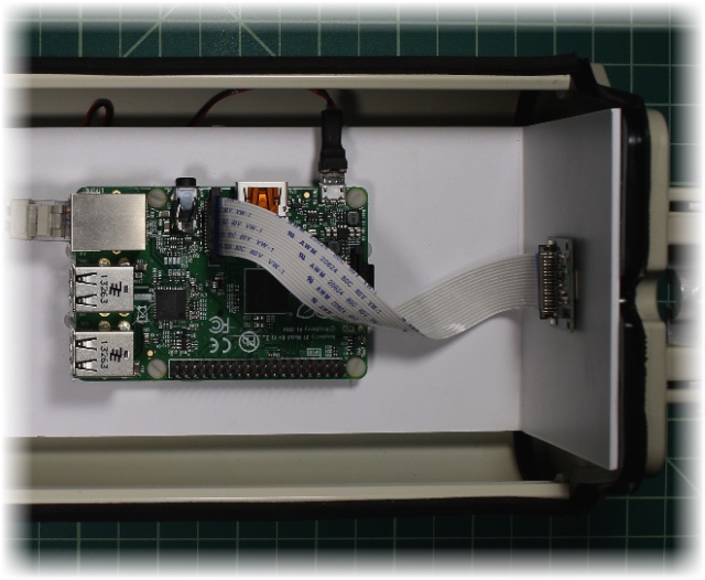
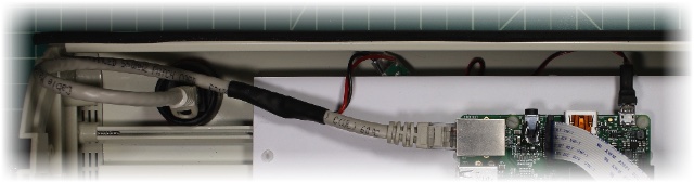
Final result
A very simple, clean build with plenty of room for future expansion. (The RGB LED and temperature/humidity sensor from the first version were dropped — they weren't very useful.)
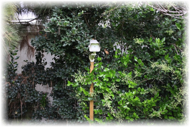
Parts & cost
| Type | Reference | Qty | Price |
|---|---|---|---|
| CPU | Raspberry Pi Model B+ | 1 | $28.48 |
| Sensor | Raspberry Pi 5 MP Camera Board Module | 1 | $25.00 |
| Camera body | Weatherproof aluminium CCTV housing (M57) | 1 | $24.99 |
| Ethernet | AEAC waterproof RJ45 coupler, F–F, 25 mm | 1 | $14.99 |
| Power supply | DC 12 V 2 A | 1 | $13.00 |
| SD card | Transcend 16 GB | 1 | $7.85 |
| DC/DC converter | UBEC, 5–23 V in → 5 V 3 A out | 1 | $4.76 |
| Power part | Huacam HCP05 passive PoE injector/splitter | 1 | $3.45 |
| Board | Styrene sheet, white, 12×12″, 0.08″ | 1 | $2.75 |
| Ethernet | Cat6 patch cable, 1 ft | 1 | $2.00 |
| Screw | Nylon 6/6 machine screw, pan head, #4-40, 1/4″ | 10 | $0.51 |
| Screw | Nylon hex standoff, male-female, #4-40, 1/4″ | 4 | $0.44 |
| Connector | Micro-USB Type A male, 5-pin | 1 | $0.39 |
| Screw | Nylon 6/6 hex nut, #4-40 | 4 | $0.23 |
| Misc | Heat-shrink tubing | 1 | $0.10 |
| Total | $128.94 |
Software installation & setup
A step-by-step installation.
Setting up the Raspberry Pi
Download and install Raspbian per raspberrypi.org/downloads. (At the time of writing I used the raw Raspbian image, release 2015-02-16.) With the micro-SD card in a USB reader, run something like:
diskutil list
diskutil unmountDisk /dev/<disk# from diskutil>
sudo dd if=path_of_your_image.img of=/dev/<disk# from diskutil> bs=1m
⚠︎ Giving a wrong device to /dev/<disk#> can wipe your computer — be extremely careful with dd. Then wait a long time, and insert the card into the Pi.
Raspbian initial settings
Connect to the new Pi and start the configuration:
$ ssh pi@<ip address>
  password: raspberry
$ sudo raspi-config
Modify the following:
- 1 — Expand Filesystem
- 2 — Change User Password
- 4 — Internationalisation Options
- I1 Change Locale — remove
en_GB.UTF-8, adden_US.UTF-8, set it as default - I2 Change Timezone — e.g. US · Pacific
- I1 Change Locale — remove
- 5 — Enable Camera
- Advanced Options → A2 Hostname →
PiCammoryGarden - Finish → Reboot now → Yes
Only step 5 is required; 1 and 2 are strongly suggested. If raspi-config doesn't offer to reboot, do it manually with sudo shutdown -r now. After rebooting, check the date/timezone with date.
Update Raspbian
$ sudo apt-get update
$ sudo apt-get upgrade
$ sudo rpi-update
A reboot activates the new firmware.
Install Netatalk & Bonjour
Netatalk is an open-source AFP file server. With it (and Bonjour), Picammory shows up in the macOS Finder and you can copy files over AFP; advertising SSH is just a nice touch.
$ sudo apt-get install netatalkRegister AFP (file sharing with the Mac):
$ sudo nano /etc/avahi/services/afpd.service

<?xml version="1.0" standalone='no'?>
<!DOCTYPE service-group SYSTEM "avahi-service.dtd">
<service-group>
    <name replace-wildcards="yes">%h</name>
    <service>
        <type>_afpovertcp._tcp</type>
        <port>548</port>
    </service>
</service-group>
Register SSH (remote shell):
$ sudo nano /etc/avahi/services/ssh.service

<?xml version="1.0" standalone='no'?>
<!DOCTYPE service-group SYSTEM "avahi-service.dtd">
<service-group>
    <name replace-wildcards="yes">%h</name>
    <service>
        <type>_ssh._tcp</type>
        <port>22</port>
    </service>
</service-group>
Restart the Avahi mDNS daemon:
$ sudo /etc/init.d/avahi-daemon restartThe Pi should now be visible in the Finder as PiCammoryGarden; connect with the pi account. Optionally, test Bonjour:
$ sudo apt-get install avahi-utils
$ avahi-browse -a | grep PiCammoryGarden
+  eth0 IPv4 PiCammoryGarden   Remote Disk Management  local
+  eth0 IPv4 PiCammoryGarden   SSH Remote Terminal     local
+  eth0 IPv4 PiCammoryGarden   Apple File Sharing      local
+  eth0 IPv4 PiCammoryGarden   Workstation             local
Install PiCamera, PIL & GPAC
PiCamera is a pure-Python interface to the camera module (Python 3.2+); PIL/Pillow is the imaging library; GPAC is the multimedia framework used for the h.264 → mp4 conversion.
$ sudo apt-get install python3-picamera
$ sudo apt-get install python3-pip
$ sudo pip-3.2 install Pillow
$ sudo apt-get install gpac
Install Picammory
Clone the sources — last released version, or the development branch:
$ git clone https://github.com/pmermoz/picammory.git ~/picammory
# or, for the development version:
$ git clone https://github.com/pmermoz/picammory.git -b develop ~/picammory
Build the C code (optional — Picammory rebuilds it at startup):
$ cd ~/picammory; python3 setup.py build_ext --inplace; cd ..Create the log folder:
$ sudo mkdir /var/log/picammory
$ sudo chown pi /var/log/picammory
Edit the configuration file:
$ cp ~/picammory/picammory.ini_template ~/picammory/picammory.ini
$ nano ~/picammory/picammory.ini| Section | Name | Description |
|---|---|---|
| [camera] | name | Name for your camera — prefixes the generated filenames |
| [smtp] | Picammory mails you system status and detection events | |
| username | Your email account username | |
| password | Your email account password | |
| usetls · server | YES for TLS; server & port (e.g. smtp.mailserver.com:587) | |
| [email] | recipient | Address(es) for the alerts |
| sender | Identifies the program (e.g. GardenCam <cam@domain.com>) | |
| [ftp] | username | FTP username — Picammory uploads videos/pictures here |
| password | FTP password | |
| server | FTP server address |
Automatic start at boot
$ sudo cp ~/picammory/etc/init.d/picammory /etc/init.d/
$ sudo chmod 755 /etc/init.d/picammory
$ sudo update-rc.d picammory defaults
Automatic restart
restartd is a daemon that watches processes and restarts one if it dies (it can take up to ~20 s).
$ sudo apt-get install restartd
$ sudo nano /etc/restartd.conf

picammory ".*picammorydaemon.py*" "service picammory restart"
Finally, reboot
$ sudo shutdown -r now